Overview
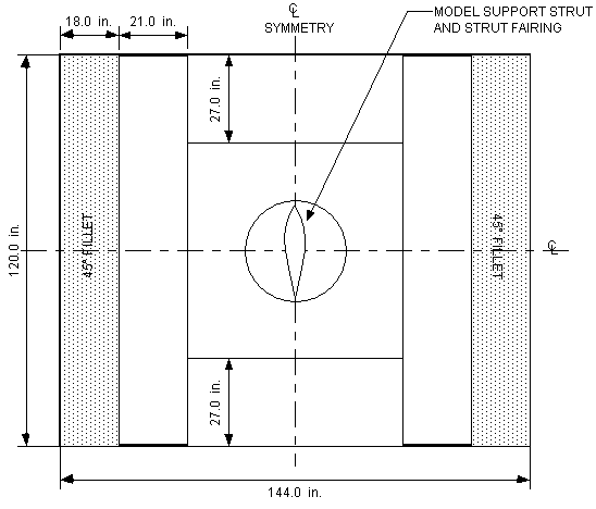
The primary aerodynamic testing facility is the F. K. Kirsten Wind Tunnel. Opened for testing in 1939, the Kirsten Wind Tunnel is of concrete construction, with seismic-reinforced brick facade. It is a double-return, closed circuit wind tunnel. The test section has a rectangular cross-section eight feet high, twelve feet wide and ten feet long, with fillets in the corners. The test section is vented to the atmosphere at its downwind end and can be viewed from all sides. Two 500-hp dc motors drive two 14 feet 9 inches diameter, seven-blade fans to provide the test section with airspeed range of about 5 to 200 mph. This provides a dynamic pressure setting range of nearly 0q to 100q for studies on typically sized wind tunnel airplane models. The tunnel is capable of airspeeds of 200 MPH with a clean test section. See Figure 1 .
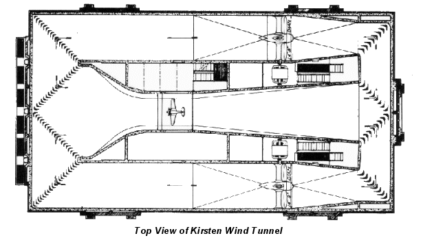
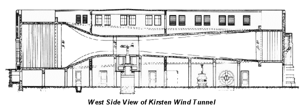
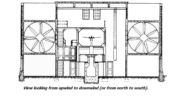
Figure 1: View of the Kirsten Wind Tunnel Building
Model mounting
Model installation
Upon delivery of the model, KWT personnel will assist in the assembly and mounting of the model. To help unload large models, a forklift is kept on-site. Once the model has been partially assembled, a hoist is used to lift the model from the ground floor and into the test section. KWT has a set of lifting eyes that can be attached to the model if the model has threaded holes at least ½” deep for a 3/8-16 bolt.
General mounting information
The model mounting strut extends from the external balance through the floor. A two- or three-point “fork” connects the mounting strut to the model by a set of pins. The strut and fork yaws with the model allowing both pitch and yaw angles to be set. The strut is covered by a streamlined fairing (see Figures 16 and 17) which does not rotate with the model. All fork attachments/fittings should be recessed into the bottom of the model surface (e.g. wing or body) and closed off with cover plates to reduce aerodynamic interference.
The pitch angle ranges for the two- and three-point mounting systems are provided in the respective drawings (see Figures 18, 24, and 25). These ranges are based on two criteria:
- The distance from center-to-center of the pitch arm pin and the model pivot point is either 5.0 or 6.0 inches.
- The model reference plane being parallel to the plane connecting all three model mounting points at zero angle of attack.
Yaw angle ranges for all mounts are approximately ± 38º. Actual pitch and yaw angle ranges depend on the model geometry.
Since the measured pitching moment cannot exceed 5,000 in.-lb., the trunnion should be near the aerodynamic center (25% MAC for an aircraft) to maximize the available range of the pitching moment due to aerodynamic loads.
Fairing dimensions
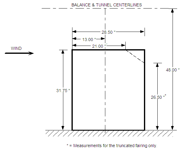
Fairing for model support strut
Fairing cross-section is a modified NACA 66-018 airfoil.
| Fairing cap | Thickness | Trailing edge |
|---|---|---|
| 4.1 | 7/8" | Non-truncated |
| 4.2 | 1-3/8" | Non-truncated |
| 4.3 | 1-3/4" | Non-truncated |
| 4.4 | 7/8" | Truncated |
| 4.5 | 7/8" | Truncated |
| 4.6 | 1-3/4" | Truncated |
To determine the total height from the test section floor, add the cap thickness to the fairing height (31.75”).
A strut base plug fouling ring can be used with fairing caps 4.3 and 4.6. It is only available for use with the Single Strut. Fouling ring thickness is 7/8” with an outside diameter of 4-1/4”. All other caps have built-in fouling circuits.
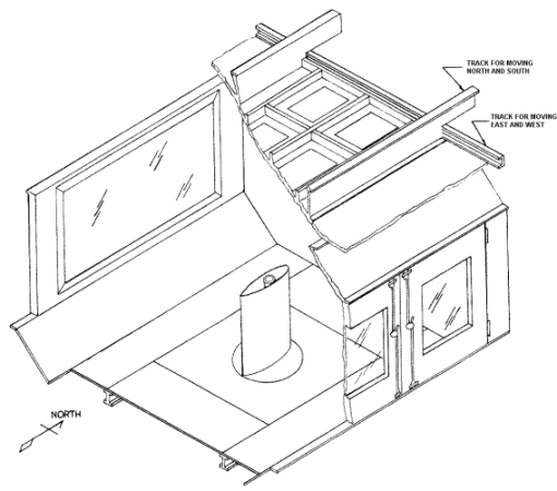
The port side of the test section is the observation deck. It provides a view of the model through a 44" x 87¼" window. The model deck also provides a view of the test section through two 28½" x 45" windows located in the two access doors. Opening both doors provides a 95" x 60" entrance to the test section.
The test section is vented to the atmosphere by two vents (5 feet long, 2 inches wide) located on the walls at the trailing edge of the test section. The vents keep the test section static pressure equal to approximately atmospheric pressure.
The upper-corner fillets have four 100-watt halogen lights on each side of the test section that can be turned on/off for obtaining the proper lighting conditions.
Two point
The two-point model mount consists of a strut and a pitch arm. There are several different types of struts available . A two-point mount is normally used for testing since it reduces aerodynamic interference and tare effects compared to a three-point mount.
The Single Strut is the usual mount for the majority of aircraft tests. It has a male clutch-face (24-tooth, 60 ° included angle) which attaches to a female trunnion block. A single bolt threads down through the trunnion block and into the Single Strut. KWT has several trunnion blocks of various sizes for use by customers. If the customer needs a special set of pins to be used with an existing trunnion block, it is recommended that the block be sent to the customer for precise fitting. Please check with KWT on availability of the trunnion blocks and pins.
Three-dimensional models exist for the trunnion blocks shown on the following pages. The parts were modeled using UniGraphics software. Electronic files containing the 3D model are available in either UniGraphics or IGES (International Graphic Exchange Standard) formats upon request.
The table below indicates the location of the trunnion with regard to the center of the test section. These values are needed for transferring moments from the balance moment center (BMC) to the desired model moment centers specified by the customer.
The Single Strut has a 0.75” diameter internal tube for routing instrumentation cables. A tall fairing cap can be installed on the fairing to cover the cables as they exit the single strut tube. This further reduces aerodynamic effects caused by the cables since they are covered by the cap.
Specialty mounting
It is not unusual for a model to need a special mount created for a test since there are no standards for the industry. If proper model drawings are provided, KWT can help in designing and manufacturing the appropriate model mount (see Auxiliary Services, Model Design/Construction).
Ground planes
To simulate ground effect for aircraft and other vehicles, a "ground plane" is placed in the test section. Several ground planes are available. The standard ground plane is a ¾”-thick plywood platform spanning the test section and extending 48 inches upstream from the center of the test section and 96 inches downstream. A leading edge extension of 24 inches can be added if needed. The vertical positions of the standard ground plane are listed below.
Standard ground plane positions
| Positions (in. from floor to top of G.P.) |
|---|
| 25-5/8 to 40-1/8 by approx. 1/4" |
| 40 5/8 |
| 40 7/8 |
| 41 1/8 |
| 41 7/8 |
| 43 1/8 |
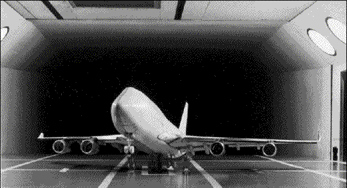
Boeing 747-400 Model with Ground Plane
Additionally, a smaller ground plane is available for use with a yaw turntable. The small ground plane measures 8-ft long, 12-ft wide and has a fixed height of 17.4 inches above the test section floor. It has a 20-inch diameter turntable. The trailing edge flap of the ground plane can be adjusted to avoid separation. This ground plane is often used for testing sailboat keels and full-scale parts, such as aircraft antennas.
Types of data
Force data
In these tests a model is mounted near the center of the test section and aerodynamic forces and moments are measured at various combinations of pitch and yaw angles at a constant airspeed. These tests use the KWT six-component external balance located beneath the test section (Figures 1 and 8).
Pressure data
These tests involve mounting a model that has pressure ports, which are read by the KWT data system. The resulting data provides a detailed pressure distribution over the model surface. These tests can use KWT-provided electronic pressure scanning (EPS) modules or individual pressure transducers.
Flow visualization data
This test is identical to a force test except forces may or may not be measured depending on the type of flow visualization technique. In either case balance data is monitored. Flow visualization tests use various methods to "show" the path of the air flow on and/or around the model. Available techniques are described in the Flow Visualization section.
Instrumentation
The electronic pressure scanning system (EPS) is the primary means for acquiring pressure data. It can support customer-supplied EPS modules from Scanivalve or Pressure Systems Inc. UWAL has two Scanivalve EPS modules: ZOC33's (64 ports, ±5psi range).
This model has an accuracy of 0.05% of the full-scale range. The system can be automatically calibrated in a matter of minutes and allows simultaneous recording of up to eight modules. Quick disconnects can be sent to the customer for plumbing of model pressures prior to model delivery.
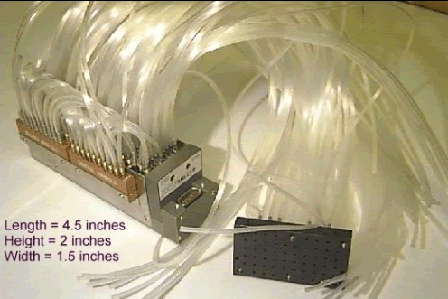
In order to use the EPS modules, the model must use pressure tubing that has an outside diameter of approximately 0.040 to 0.042 inches. Stainless steel tubing is normally used to make the pressure ports in the model. Plastic tubing connects the steel pressure port tubing to the EPS module (urethane plastic tubing is recommended).
Reynolds measurement
The dynamic pressure in the test section is measured by a precision differential pressure transducer: Mensor model DPG II 1500. It has a full-scale range of ±0.75 psi, with an accuracy of ± 0.01% of full scale. The transducer is calibrated every six months using a primary standard traceable to the National Institute of Standards & Technology (NIST).
The static pressure in the test section is measured by an absolute pressure transducer: Omega model PX425-030AV. It has a full-scale range of 0 to 30 psi with an accuracy of ±0.05 % of full scale.
Test section temperature RTD
The test section static temperature is measured by a Resistive Temperature Device (RTD), manufactured by National Semiconductor. It has a full-scale range of 5 to 300 degree Fahrenheit with an accuracy of ± 1 degree Fahrenheit.
Primary balance
The main balance is a six-component (three forces, three moments) external balance located beneath the test section floor. The balance simultaneously measures all forces and moments with respect to the wind axes at the virtual balance moment center located at the center of the test section. These forces and moments are converted to voltages by electromagnetic potentiometers. The output voltages are amplified and converted to digital numbers in engineering units. The balance limits are:
Balance resolution and limits
| Balance Component | Resolution | Full Scale Limit |
|---|---|---|
| Lift | 0.090 lbs | 2,500 lbs |
| Drag | 0.013 lbs | 250 lbs |
| Side Force | 0.01 lbs | 250 lbs |
| Pitching Moment | 0.232 in-lbs | 5,000 in-lbs |
| Yawing Moment | 0.205 in-lbs | 5,000 in-lbs |
| Rolling Moment | 0.169 in-lbs | 5,000 in-lbs |
The external balance has passive damping for reducing vibrations induced by the model. All signals from the external balance are sent through a 1 Hz low-pass filter before being sent to the data acquisition computer.
A breeze shield protects the external balance area from the effects of drafts.
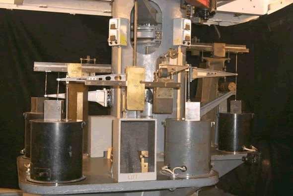
6-component external balance
Data reduction
Test Section Conditions
A detailed upflow and dynamic pressure calibration of the test section was conducted using a five-hole probe and a NACA 0015 wing to determine the flow qualities. The upflow angle is -0.012° for normal tests. Testing with calibration and commercial models have shown a negligible crossflow. A detailed survey of the test section using a hot-wire anemometer shows a nominal turbulence intensity of 0.72%. The average year-round temperature is 52.0°F with an average pressure of 2090.2 psf (readings taken from SeaTac International Airport).
Auxiliary services
Model design/construction
KWT has aeronautical engineers who can assist in the design and supervision of manufacturing model parts through the Department of Aeronautics & Astronautics machine shop. For larger projects involving the design and construction of complete models, local model builders can be subcontracted.
Office space
We have copying, printing, meeting and other services necessary to support our customers while the test is running.
Pre-engineering
- Model design
- Shop services and model building
- Instrumentation install