
Hardware
The data system consists of a dual-processor 150-MHz Pentium Pro PC with a 16-bit analog-to- digital converter. It is networked with all other computers in the computer room using a Microsoft Windows NT network. To avoid network interference, a serial cable is used to transfer data between the on-line plotting PC and the data acquisition PC immediately after it has been recorded.
Data processing
The data system nominally has 6 extra data channels for customer use. Each channel of the data acquisition system has an associated signal conditioner and amplifier. Data is taken and averaged at a sampling rate of 100 samples per second. Data is only taken if the dynamic pressure is on-condition, i.e. if the dynamic pressure is within 1% of the target value. Each test point consists of five seconds of on-condition data. The on-condition criteria can be changed to meet individual test requirements, for example, on-condition only if the velocity is within 1 ft/sec.
Daily calibration process
In order to maintain the integrity of the data, a balance calibration is conducted twice a day by hanging check weights at half-scale for each component. The calibration (BALCAL) includes a system calibration (SYSCAL). The system calibration automatically checks and corrects the amplifier outputs and analog-to-digital converter (ADC) using a programmable voltage
standard (PVS). The operator is notified if any portions of the data acquisition system provide outputs that are out of pre-established tolerances.
Model positioning
Model Accelerometer mount
The data acquisition system moves the model through a preprogrammed set of angles. The list of desired angles can be a series of subsets. An example for pitching the model: -10° to - 2° by 2°, -2° to +2° by 1°,+2° to 32° by 4°. Furthermore, if the actual angle of the model is not within ±0.02° of the target angle, the system can be setup to retry until the actual angle is within tolerance. The tolerance can be re-defined by the operator.
The model positioning motors move the model at a yaw rate of 1° per second and a pitch rate of 2° per second (for the standard five-inch distance between trunnion and pitch arm attachments).
A model position calibration is conducted for each model. Angles of yaw are measured after determining the yaw = 0° point. Angles of attack are measured by an internal model accelerometer. Each model should be built with a cavity for housing the KWT model accelerometer.
Drawing of Inclinometer base and front view
If the model cannot accommodate the internal model accelerometer, the angles of attack are determined by an encoder that measures the position of the pitch arm. The encoder reading is correlated to the model angle of attack using a precision inclinometer (±0.01° resolution). The calibration provides angles of attack to within 0.02°. See detailed drawing of the KWT inclinometer, this is to be used in creating a mounting block for the customer’s model. The customer is responsible for providing a reference surface for placement of the inclinometer.
Auxiliary instrumentation
Inputs to the system may be either full or half bridge resistive transducers or dc voltages. Transducer excitation is normally 5 or 12 volts. The amplifiers are gain switchable in ten steps to give a full scale input from 8 to 245 millivolts. In addition, the amplifiers have a ten step low pass filter with cutoffs from 1/8 to 256 Hz, normally set at 1 Hz.
DAQ upgrades
The Kirsten Wind Tunnel has recently finished the installation of a new data acquisition and signal conditioning system (DAQ). The new system is currently running in conjunction with the old DAQ as a means of testing and validating its performance with plans to switch over entirely in the next year.
The new DAQ, predicted to be state of the art for at least the next 5-10 years, is a PC controlled National Instruments PXIe chassis system. The PC acquisition control allows for minimal down time following any failures or upgrades. A total of 18 modules are included with the PXIe chassis system, all of them can perform a different function and can be synchronized to a common backplane timing source. The hardware complexity required for the old DAQ has been greatly simplified in the new DAQ with the inclusion of analog measurement modules that contain all necessary signal conditioning.
The New DAQ will support all of the following signal types:
- Differential Analog Voltage Input
- Full Bridge, Half Bridge, Quarter Bridge Sensors
- Current Sense (user supplied current sense resistors)
- Potentiometers
- RTDs (in bridge circuit)
- Quadrature Encoders
- Frequency/Counter Inputs
- 32-Bit Digital Input
- 32-Bit Digital Output
This upgrade will improve the wind tunnel by providing a platform and foundation for easy future updates to data acquisition software, a simple way to stream all data straight to TCAM (Test Control and Acquisition Modulus), easy integration with any type of sensor, and capabilities to set channel limits, EU constants, digital filters, etc.
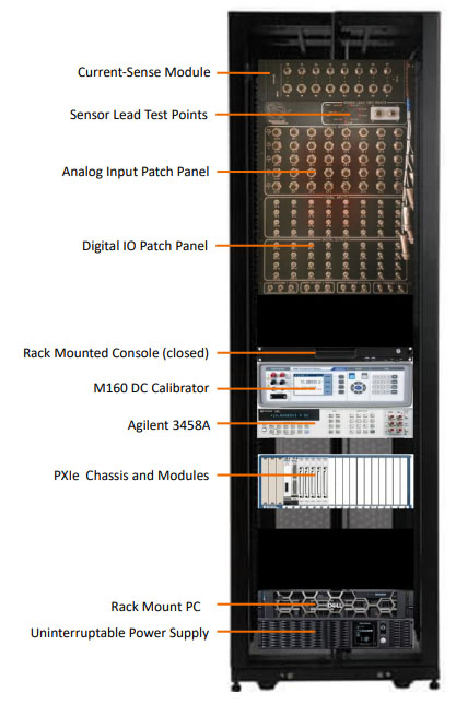
New DAQ system in 42U enclosure.