
Model Installation
Upon delivery of the model, KWT personnel will assist in the assembly and mounting of the model. To help unload large models, a forklift is kept on-site. Once the model has been partially assembled, a hoist is used to lift the model from the ground floor and into the test section. KWT has a set of lifting eyes that can be attached to the model if the model has threaded holes at least ½” deep for a 3/8-16 bolt.
General Mounting Information
The model mounting strut extends from the external balance through the floor. A two- or three-point “fork” connects the mounting strut to the model by a set of pins. The strut and fork yaws with the model allowing both pitch and yaw angles to be set. The strut is covered by a streamlined fairing (see Figures 16 and 17) which does not rotate with the model. All fork attachments/fittings should be recessed into the bottom of the model surface (e.g. wing or body) and closed off with cover plates to reduce aerodynamic interference.
The pitch angle ranges for the two- and three-point mounting systems are provided in the respective drawings (see Figures 18, 24, and 25). These ranges are based on two criteria:
1) The distance from center-to-center of the pitch arm pin and the model pivot point is either 5.0 or 6.0 inches.
2) The model reference plane being parallel to the plane connecting all three model mounting points at zero angle of attack.
Yaw angle ranges for all mounts are approximately ± 38º. Actual pitch and yaw angle ranges depend on the model geometry.
Since the measured pitching moment cannot exceed 5,000 in.-lb., the trunnion should be near the aerodynamic center (25% MAC for an aircraft) to maximize the available range of the pitching moment due to aerodynamic loads.
Fairing for model support strut
Fairing cross-section is a modified NACA 66-018 airfoil.
To determine the total height from the test section floor, add the cap thickness to the fairing height (31.75”).
A strut base plug fouling ring can be used with fairing caps 4.3 and 4.6. It is only available for use with the Single Strut. Fouling ring thickness is 7/8” with an outside diameter of 4-1/4”. All other caps have built-in fouling circuits.
Three Point
The standard model mount consists of a "V" shaped yaw fork and a pitch arm (see Figures 17 and 18). The model pitches about the upper end of the yaw fork and the whole assembly rotates in yaw. Fitting Nos. 3 and 4 are usually used with the yaw forks and No. 2 for the pitch arm when mounted in a wing.
The yaw forks designated by -H place the model trunnion at the balance moment center. The -H yaw forks usually mount into the wing (for wing alone model build up). For large models, yaw forks 10-H or 14-H are recommended since they are stiffer in yaw and roll.
The two yaw forks designated -L place the trunnion five inches below the balance moment center. The -L forks can be used for a high wing model with a deep fuselage to keep the wing near the tunnel centerline.

Fork with pitch arm

Model Mounting Forks

Model mount fork attachments
Two Point
The two-point model mount consists of a strut and a pitch arm. There are several different types of struts available . A two-point mount is normally used for testing since it reduces aerodynamic interference and tare effects compared to a three-point mount.
The Single Strut is the usual mount for the majority of aircraft tests. It has a male clutch-face (24-tooth, 60 ° included angle) which attaches to a female trunnion block. A single bolt threads down through the trunnion block and into the Single Strut. KWT has several trunnion blocks of various sizes for use by customers. If the customer needs a special set of pins to be used with an existing trunnion block, it is recommended that the block be sent to the customer for precise fitting. Please check with KWT on availability of the trunnion blocks and pins.
Three-dimensional models exist for the trunnion blocks shown on the following pages. The parts were modeled using UniGraphics software. Electronic files containing the 3D model are available in either UniGraphics or IGES (International Graphic Exchange Standard) formats upon request.
The table below indicates the location of the trunnion with regard to the center of the test section. These values are needed for transferring moments from the balance moment center (BMC) to the desired model moment centers specified by the customer.
| TRUNNION BLOCK | X (in) | Z (in) |
|---|---|---|
| Small | 0.0 | 0.0 |
| Large | 0.0 | 0.0 |
| Offset | -1.38 | -0.137 |
| Low Profile | 0.0 | -0.986 |
The Single Strut has a 0.75” diameter internal tube for routing instrumentation cables. A tall fairing cap can be installed on the fairing to cover the cables as they exit the single strut tube. This further reduces aerodynamic effects caused by the cables since they are covered by the cap.

Single Strut With Pitch Arm Installed (2-point mount)

Small Trunnion Block Specifications for Single Strut
Large Trunnion Block Specifications for Single Strut
**********************************************************************************

Single Strut Dimensions
The pitch arm shown in the graphic below is representative of pitch arms at KWT but should not be used for model design purposes. Please contact KWT for information about the specific pitch arm you are interested in using, or download the CAD files.

Boeing Single Strut (most common)

Pitch arm #7-2
One Point
Any of the single struts can be used to support a model from a single point. A one-point mount should only be used with small models at low airspeed to minimize the chance of structural failure.
Another possibility is to mount the model directly to a yaw turntable that lies flush with the 8’ x 8’ ground plane. The turntable is three feet in diameter and sits 6.25 inches above the test section floor. A yaw turntable allows for ±30° of yaw. By mounting the model to a second plate that mounts to the first turntable, the orientation of the two plates can be changed to allow for 180° of yaw.
Special Mounting Systems
It is not unusual for a model to need a special mount created for a test since there are no standards for the industry. If proper model drawings are provided, KWT can help in designing and manufacturing the appropriate model mount (see Auxiliary Services, Model Design/Construction).
Ground Planes
To simulate ground effect for aircraft and other vehicles, a "ground plane" is placed in the test section. Several ground planes are available. The standard ground plane is a ¾”-thick plywood platform spanning the test section and extending 48 inches upstream from the center of the test section and 96 inches downstream. A leading edge extension of 24 inches can be added if needed. The vertical positions of the standard ground plane are listed below.
Standard Ground Plane Positions
| Positions (in. from floor to top of G.P.) |
|---|
| 25-5/8 to 40-1/8 by approx. 1/4" |
| 40 5/8 |
| 40 7/8 |
| 41 1/8 |
| 41 7/8 |
| 43 1/8 |
Boeing 747-400 Model with Ground Plane
Additionally, a smaller ground plane is available for use with a yaw turntable. The small ground plane measures 8-ft long, 12-ft wide and has a fixed height of 17.4 inches above the test section floor. It has a 20-inch diameter turntable. The trailing edge flap of the ground plane can be adjusted to avoid separation. This ground plane is often used for testing sailboat keels and full-scale parts, such as aircraft antennas.
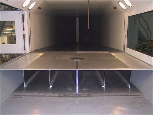
8’ by 12’ Keel Ground Plane With 20” Diameter Turntable
Due to its infrequent usage, the 8’ by 12’ Keel Ground Plane with 20’’ Turntable is stored in a UW warehouse off campus, and so its availability needs to be verified each time before UWAL commits to its use. Call for status.