Every day the future is being expanded in our labs. From the development of advanced unoccupied aerial vehicles to new aerodynamic techniques and unconventional space propulsion concepts, the faculty and students of UW Aero & Astro are honing the cutting edge of tomorrow's technologies.
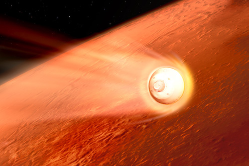
Space Systems
Off-planet activities requiring advances in current technology to support long-term operations in space.
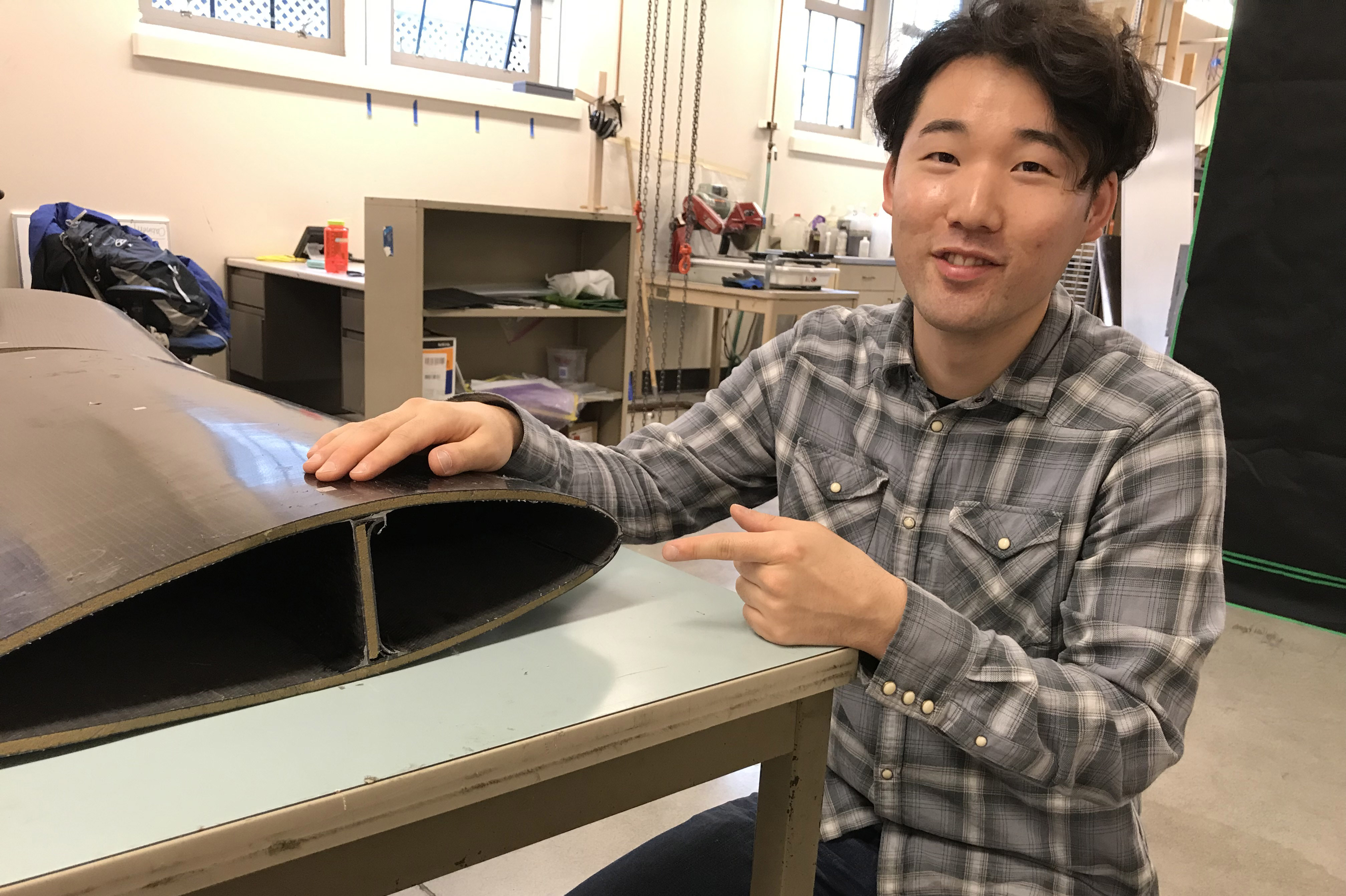
Structures & Composites
Engineered advanced materials and adaptive structures for sustainable terrestrial and space travel, security and habitation.
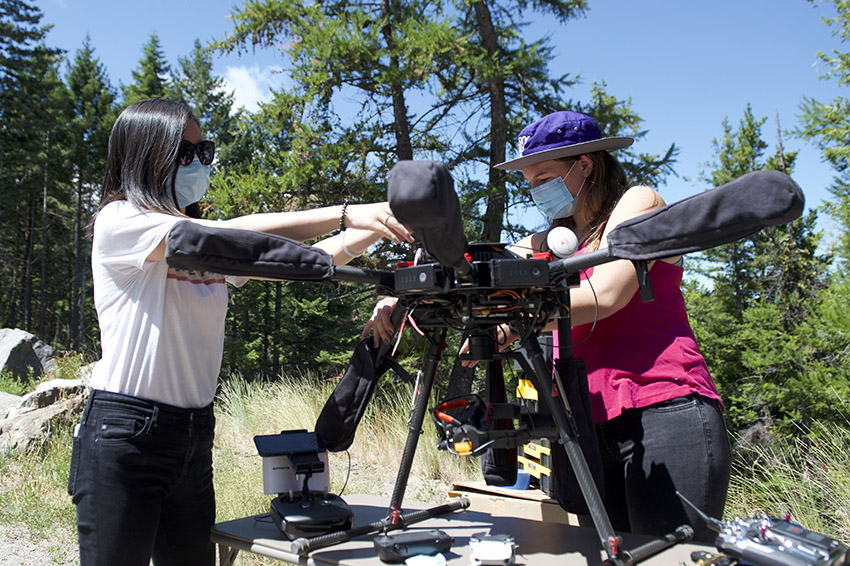
Controls
The design of algorithms and techniques to enable systems to independently perceive, reason, and act within their environment.
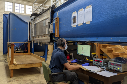
Integrated Flight Sciences and Control
The combination of structures, aerodynamics, and controls for designing advance aerospace vehicles.
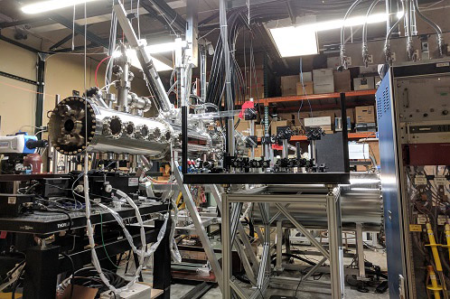
Plasma Science
The fundamental study of the fourth state of matter for applications in fusion, deep space propulsion and space science.
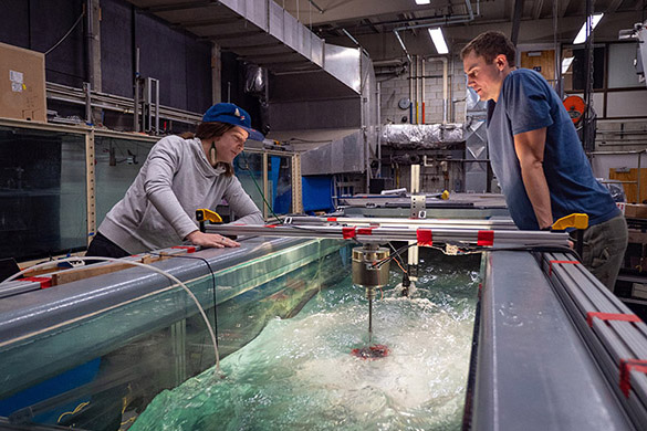
Fluids
Aerodynamics, thermodynamics, turbulence and mixing with applications in propulsion, flight and energy.
If you are interested in connecting with faculty or sponsoring a research project, please contact A&A's External Relations to set up a department visit.